Projects
Servo-Driven Animatronic Bird – Inspired by the Enchanted Tiki Room
Project At a Glance
Fully articulated animatronic figure with multi-axis servo motion
Designed, fabricated, assembled, and programmed end-to-end
Embedded Teensy-based control with homing routines, software end-stops, and motion limits
CNC, waterjet, laser-cut, and production-intent 3D printed components (PETG, nylon)
Functional prototype complete; currently focused on theming and installation design
Personal Engineering Project | In Progress
Ahh, the Tiki Room — a longtime favorite attraction of mine at Disney (very underrated, in my opinion!). My family has a particularly fond story from when I was younger. I remember seeing the Tiki Room walking into Adventureland. I always wanted to know what it was about (the promise of tikis and lit torches never hurt either!).
Anyway, I kept asking my family if we could try out the Tiki Room. To which they would always say, “No!” Eventually, later in the day — hot, sweaty, and tired — they finally relented under my pressure, and we went into the Tiki Room.
What happened took all of us by surprise. The whole room came to life — the song, the birds, the plants, the tikis... even the walls! My dad couldn’t stop laughing. We were all just in amazement.
To this day, I always make time to visit the Tiki Room. It’s an incredible piece of show engineering from Disney. And from a purely mechanical engineering standpoint, it’s stunning. So I decided that, as a personal engineering project, I would build my own Tiki Room–inspired parrot, based on José — both to demonstrate and expand my engineering skills.
System Overview
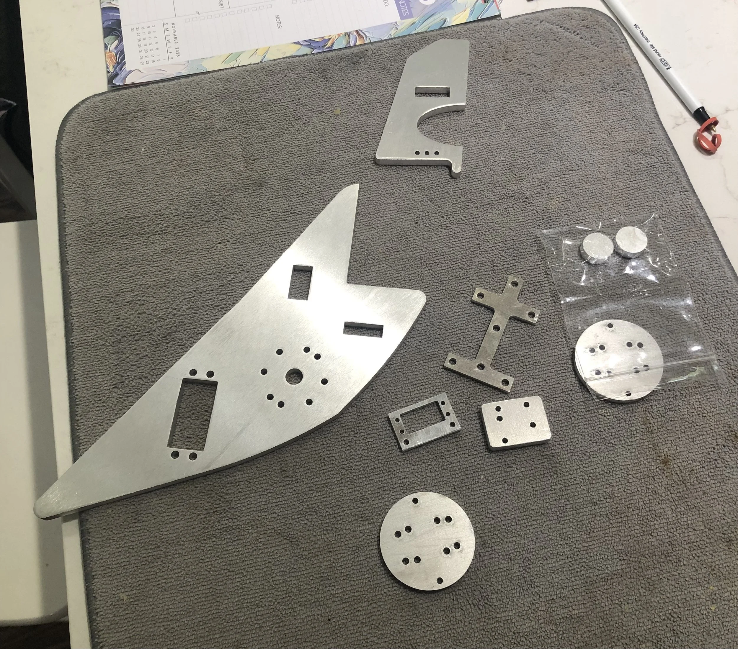
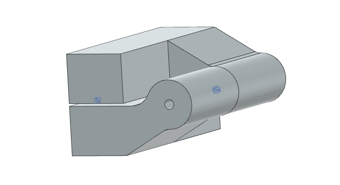
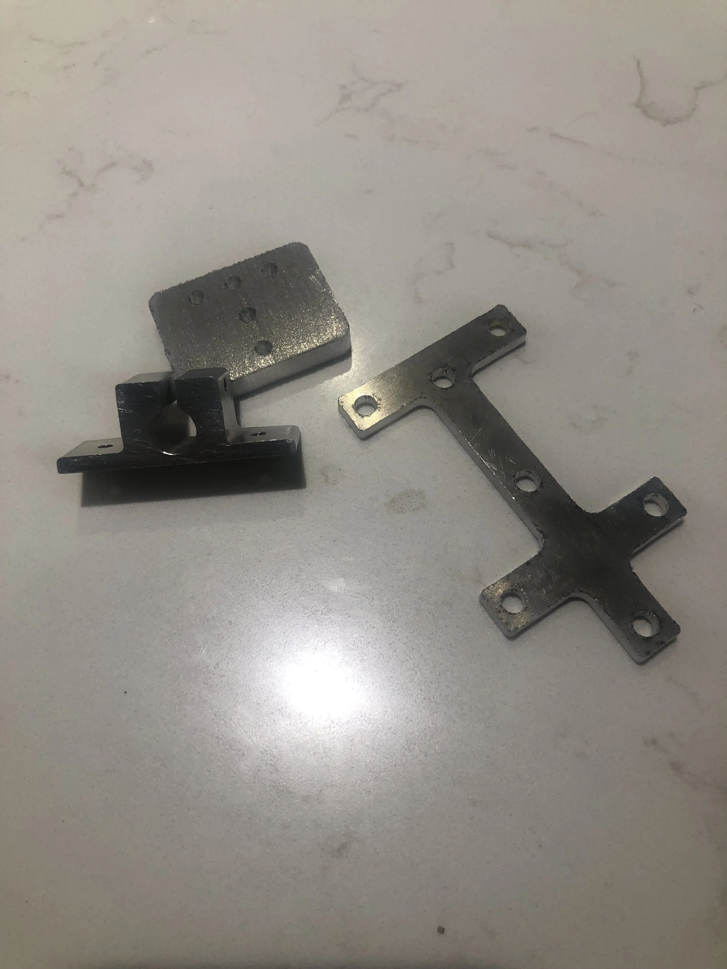
NX Assembly and water jet/ laser cut parts

Project Status, Integration & Next Steps
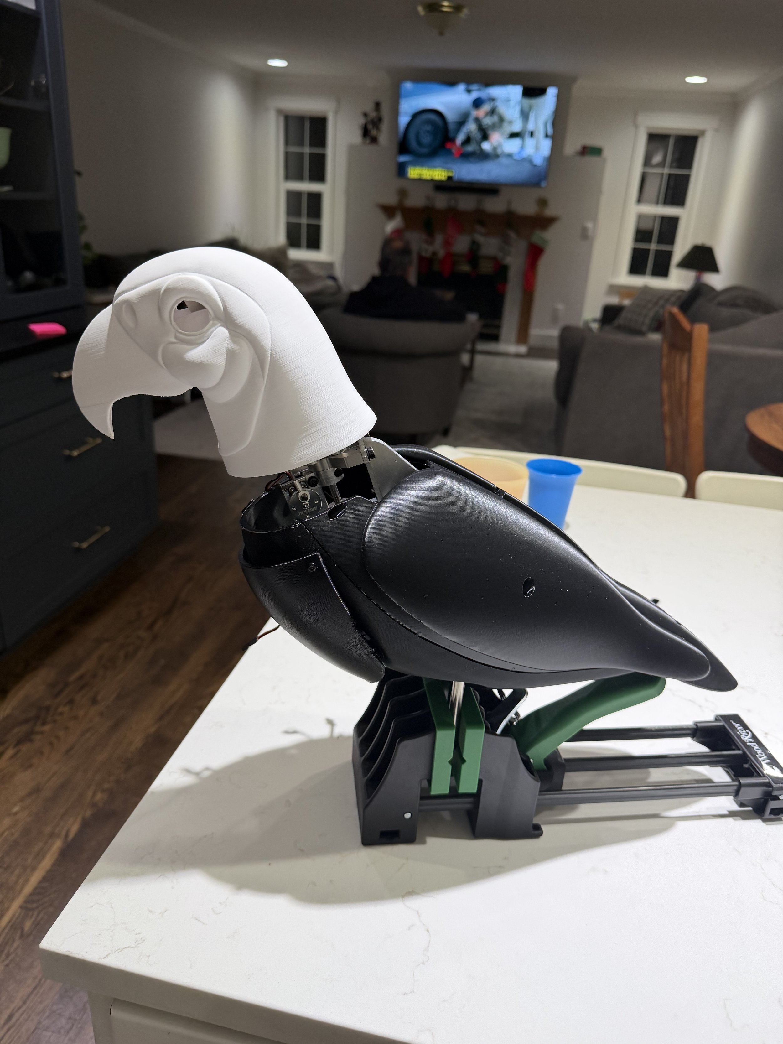
This project is now in the functional prototype and system integration phase, with all bird mechanical components fabricated, assembled, and operational. Multi-axis motion (head swivel, tilt, beak actuation, and chest movement) has been physically realized and validated through software-controlled motion testing.
A Teensy-based embedded control system has been developed to manage servo homing, software end-stops, motion limits, range-of-motion constraints, and speed profiles, ensuring safe, repeatable, and lifelike movement.
System Completion Summary
Servo selection is complete, structural components have been manufactured via CNC machining and waterjet cutting, and the external shell has been fully sculpted, printed, and integrated. Final integration and installation-focused fabrication is currently underway.
Servo Selection & Finalization
(Completed)
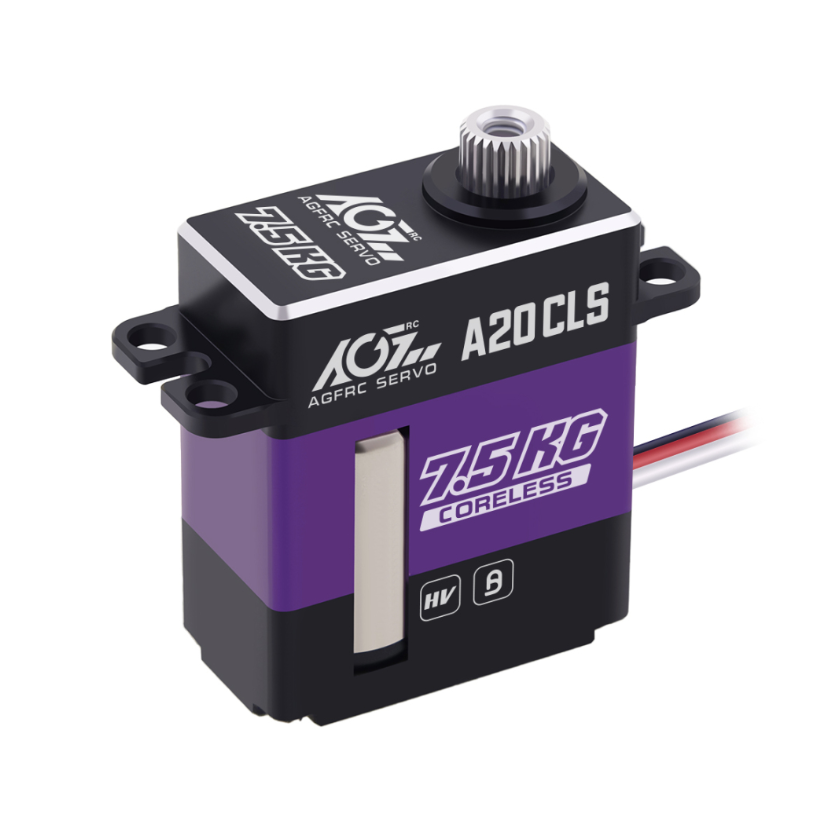
Four digital servos were selected to handle a range of force and motion requirements across the animatronic subsystems:
AGFRC A20CLS (×2): Selected for tilt actuation and head turning, offering a compact aluminum case, programmable response curve, and high-voltage digital performance suitable for fast directional changes under moderate load.
AGFRC A80BHSW: Chosen for the body rotation mechanism due to its 36 kg high torque rating, brushless motor, and IP67 waterproofing. Its holding strength ensures smooth, stall-resistant rotation for the central structure.
KST X08 (×2): Lightweight and ultra-slim, these digital servos drive the beak actuation and chest movement, providing quiet motion, precise response, and low-profile integration in tight spaces.
Manufacturing & Tooling
(Mechanical Systems - Completed, Perch Assembly - In Progress)
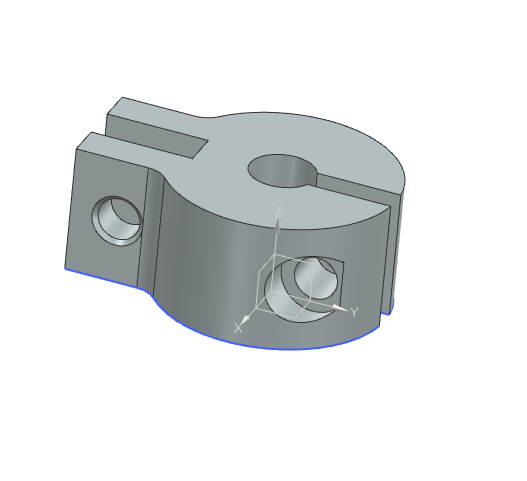
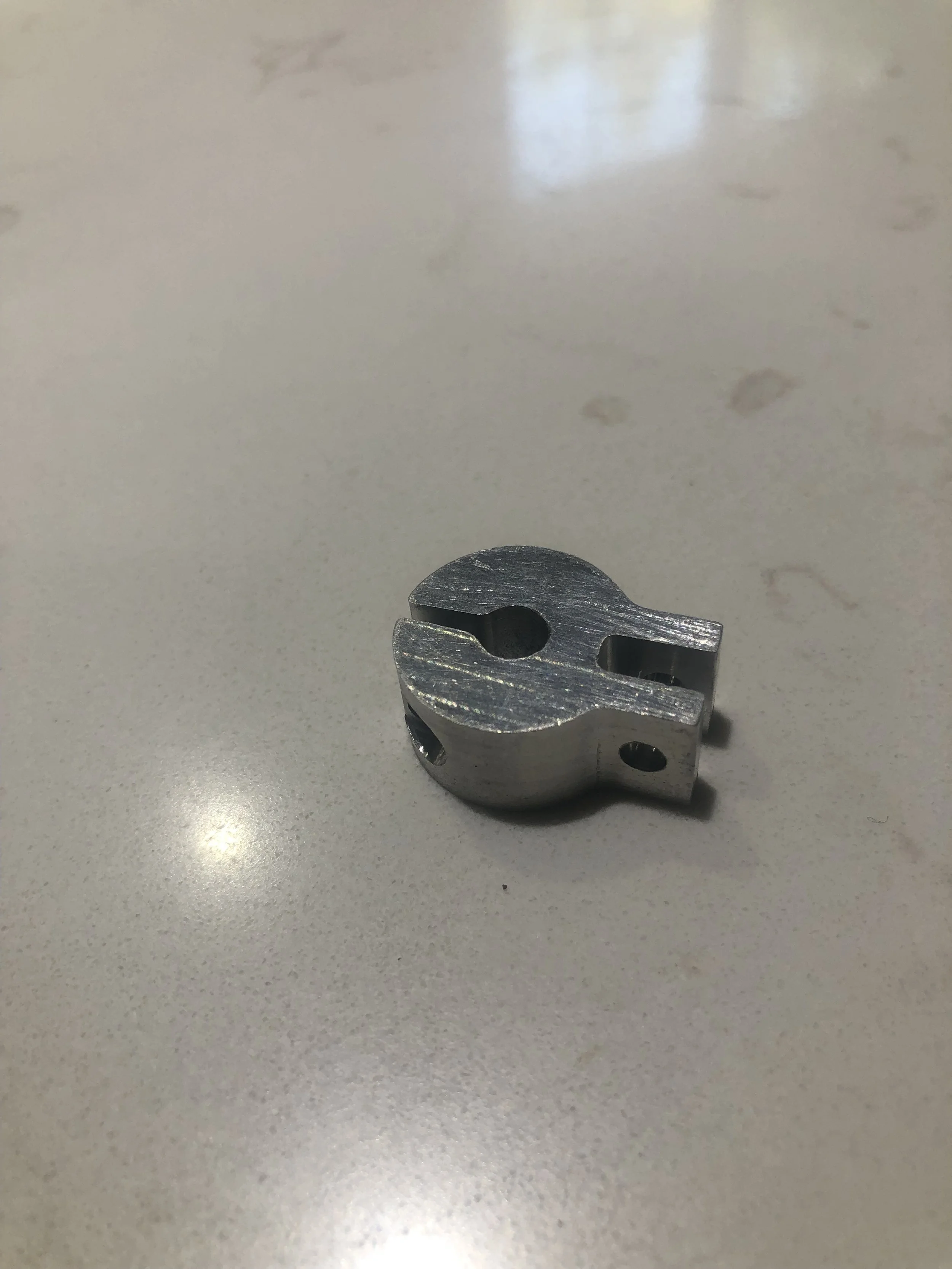
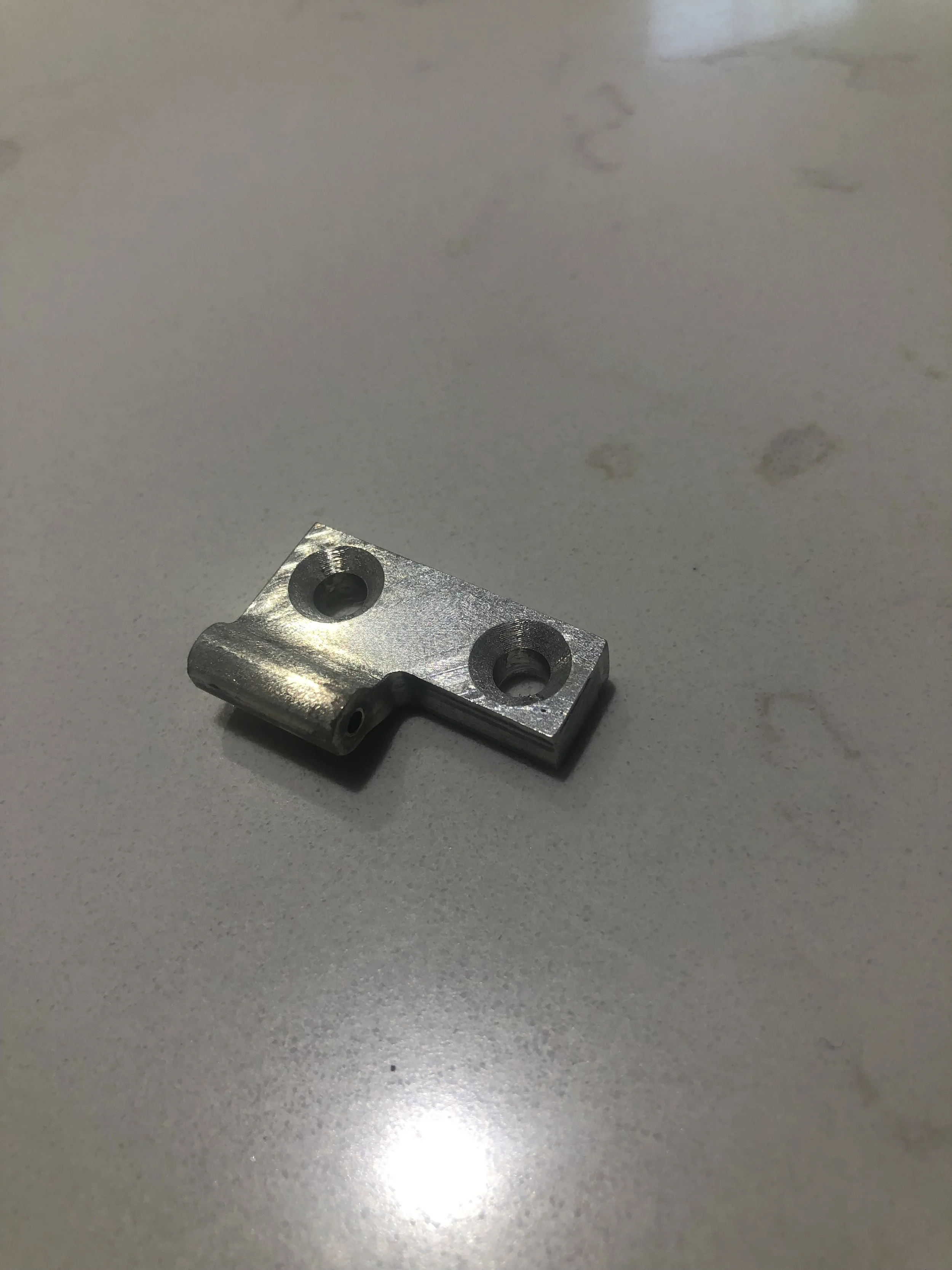
Structural components were fabricated using waterjet cutting, CNC machining, and laser cutting. Additional operations were performed personally using a mill and lathe to produce perch components, internal clamp hardware, and precision features. Custom drill jigs were designed and 3D printed to ensure accurate hole placement and repeatable assembly.
Additive Manufacturing & Shell Integration
(Completed)
The external shell has been fully 3D printed using PETG on a Bambu X1 Carbon, transitioning from PLA prototypes to production-intent material. Sculpt refinements were performed in Fusion 360 and Blender to integrate internal bosses, electronics mounts, heat-set inserts, and service access points.
Heat-set threaded inserts were installed to enable repeatable assembly and serviceability. Aesthetic modifications were made to support the installation of taxidermy eyes, requiring mesh cleanup and geometry edits.
Motion & Controls Testing
(Ongoing)
Early motion testing was performed to validate servo limits, software end-stops, homing routines, and coordinated movement profiles. These tests confirm safe operation within mechanical constraints prior to final show tuning.
Remaining Work:
Design and fabricate perch suspension arms with concealed load paths
Engineer a ceiling mounting solution emphasizing safety, serviceability, and vibration isolation
Complete show theming and visual integration
Final motion tuning and synchronization
These next steps focus on refining motion quality, structural simplicity, and production feasibility — while staying true to the character-driven performance of Disney’s original Audio-Animatronics.
| • Multi-axis motion design | • Bracket and hinge evaluation for rotating assemblies |
| • GD&T in NX | • Servo load analysis |
| • Tolerance stack-up planning | • Siemens NX modeling |
| • DFM principles (machined & printed parts) | • Creative problem-solving |
| • Servo selection and torque balancing | • Custom clamp and collar design |
| • Motion linkage design (clevis, push/pull) | • Component integration planning (A20CLS, A80BHSW, KST X08) |
| • Precision fabrication prep (drilling, tapping, reaming) | • Makerspace manufacturing strategy & drill jig design |
| • CNC, waterjet, and laser-cut part integration | • Custom threaded linkage rod development |
| • Additive manufacturing DFM (PETG, nylon, heat-set inserts) | • ZBrush, Fusion 360, and Blender workflow for shell integration |
| • Embedded firmware development (Teensy, homing, limits) | • Mechatronics system integration & motion validation |
Engineering Skills Used
Servo Motion & Software Limits Test
Teensy-controlled homing, end-stops, and speed profiling.


Project Stage & Technical Summary
This project has progressed through detailed mechanical design, fabrication, and system integration, and now exists as a functional, fully articulated animatronic prototype. All primary motion subsystems—including head swivel, tilt, beak actuation, chest breathing motion, and body rotation—have been designed, fabricated, assembled, and validated through software-controlled testing.
Full 3D CAD assemblies were developed in Siemens NX, followed by fabrication using 6061-T6 aluminum components produced via waterjet cutting, CNC machining, and laser cutting, alongside production-intent 3D printed shells in PETG. Custom linkages, precision fits, and serviceable assemblies were incorporated to support repeatable motion and long-term maintainability.
Embedded control software running on a Teensy microcontroller manages servo homing, software end-stops, motion limits, and speed profiles, enabling safe, repeatable, and lifelike motion. Physical testing has validated mechanical clearances, linkage behavior, and motion ranges prior to final show tuning.
The current phase of the project focuses on installation-level engineering and theming, including perch suspension design, ceiling mounting strategies, vibration isolation, and final motion refinement. Overall, this project reflects a complete end-to-end engineering workflow—combining precision mechanical design, mechatronics, embedded control, and character-driven performance—closely mirroring the multidisciplinary work of Imagineering and advanced mechanical systems teams.
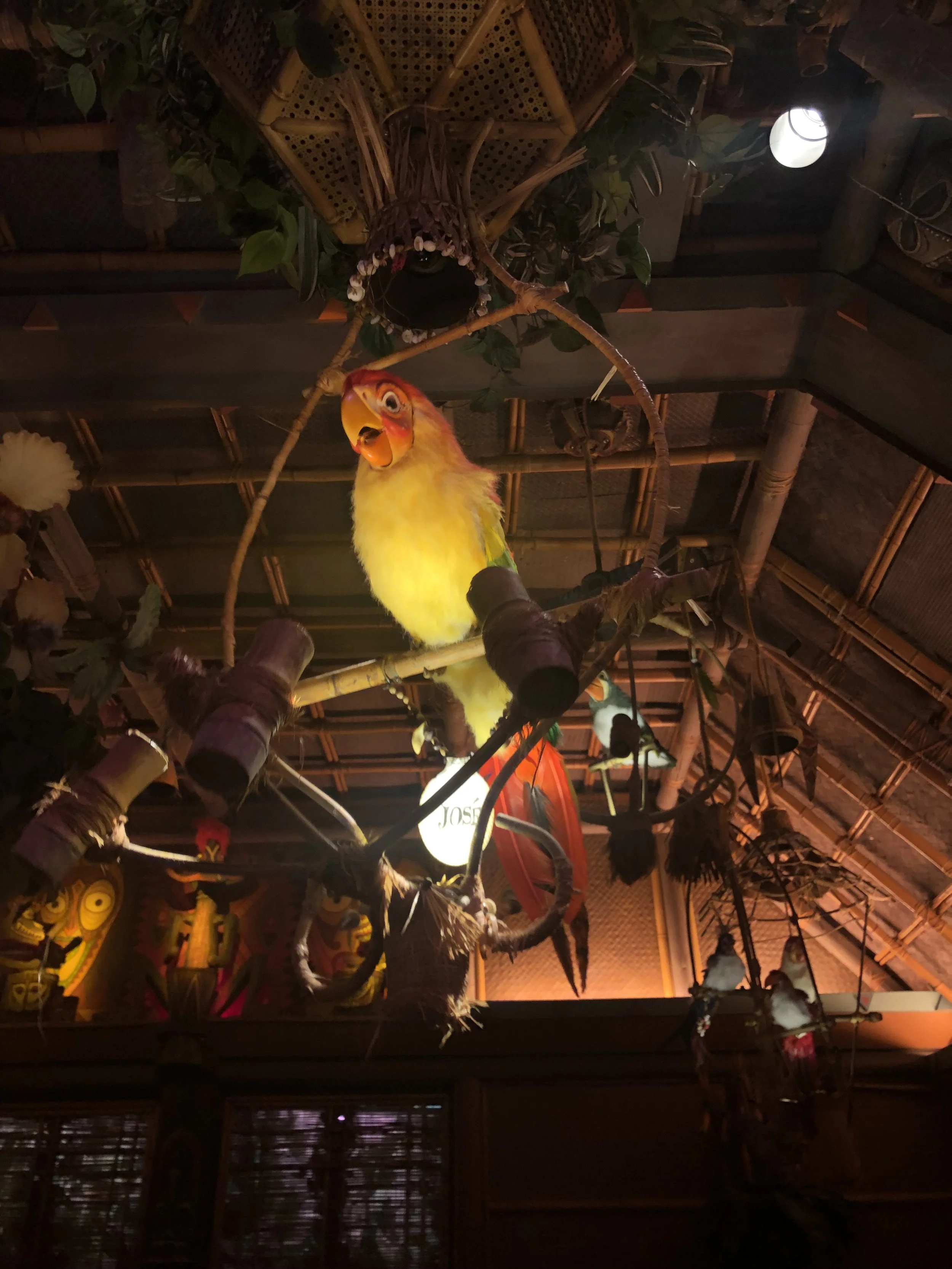
Inspiration reference: José from Disney’s Enchanted Tiki Room. This project is a personal engineering build and is not affiliated with or endorsed by The Walt Disney Company.
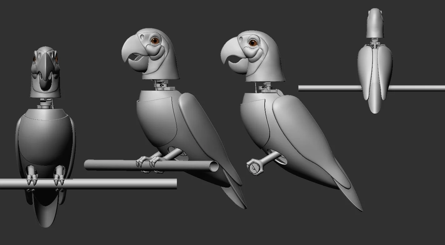
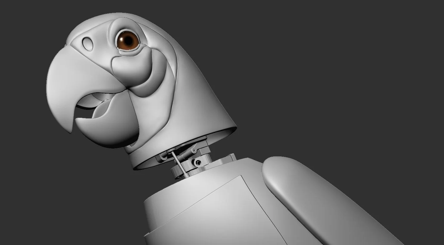
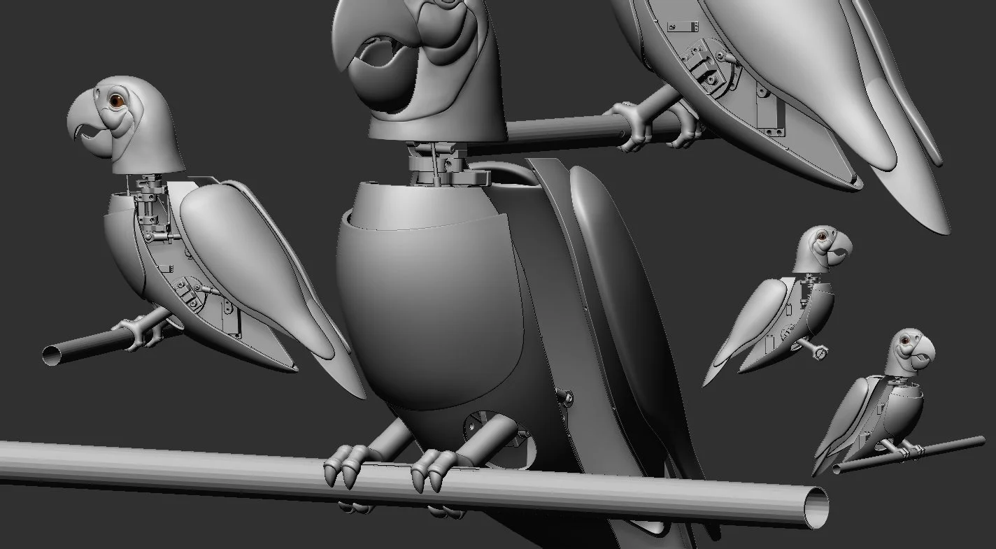
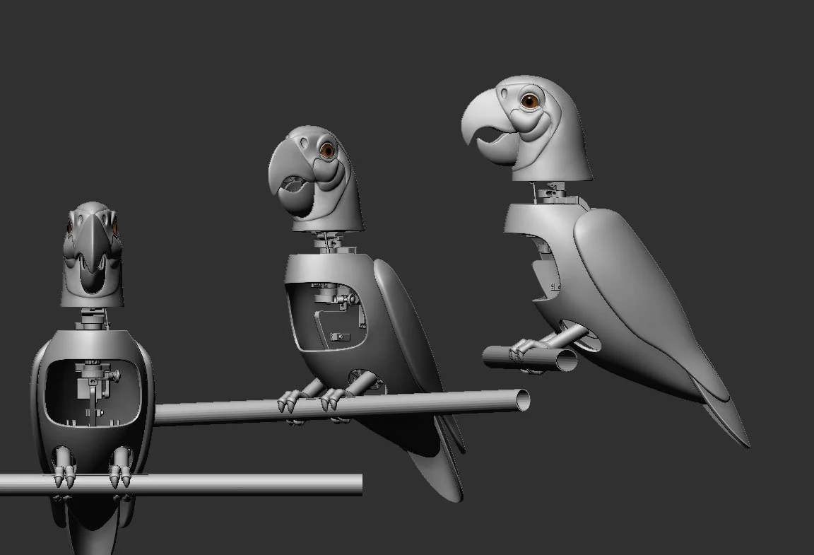
ZBrush Sculpt done by a freelancer to fit the internal mechanical components
This personal project explores multi-axis motion control for an animatronic bird. It serves both as a themed entertainment prototype, demonstrating the principles of show engineering used at Disney Imagineering, and as an engineering exercise in precision mechatronics, manufacturability, and servo-driven system integration—skills equally applicable to aerospace and advanced mechanical design. The animatronic bird is now mechanically complete and fully articulated, with all motion axes assembled and operational.
A rotating shaft for head swivel (Completed)
A stacked tilt mechanism actuated via linkage (Completed)
A servo-embedded beak movement system (Completed — refinement ongoing)
A chest puffing mechanism driven by a micro-servo (Completed)
The design uses Sonic Hubs and flanged bearings to suspend the gimbal assembly and is constructed from 6061-T6 aluminum for strength and machinability. Fabrication has included waterjet-cut frame plates, CNC-machined brackets, and custom threaded linkage rods to connect servo horns with clevis joints.
Ongoing development includes:
Servo selection (Completed) and power balancing (In Progress)
Clamp hinge integration for head tilt (Completed)
Torsion spring and hinge refinement for beak actuation in a constrained space (In Progress)
Perch/body rotation mechanics with hidden stainless steel leg supports (In Progress)
Tolerance stack-up planning and precision reaming for mechanical clearance (In Progress)
Final linkage and actuation tuning for smoother, lifelike motion (In Progress)
Electronics integration with Teensy-based servo control, wiring routed through the legs, and provisions for future mic/speaker installation (Core complete; expansion in progress)
This project emphasizes real-world design-for-manufacturability (DFM), integrated mechatronic systems, and character-driven motion—combining Imagineering-style show engineering with hands-on fabrication and real-world build practice.
University Keystone Senior Design Project
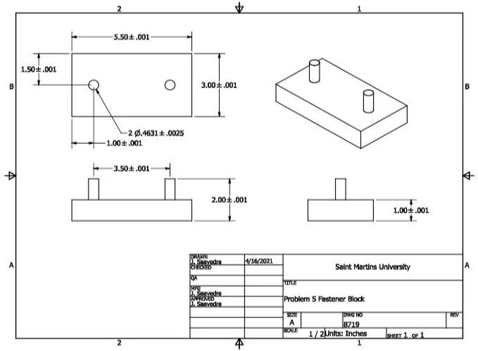
This Project was done in the years 2020-2021 as a keystone project for Saint Martins University. The Project was to design a device that was ergonomic and facilitated the ability to girdle trees in an efficient manner on tree farms for the Washington State Department of Natural Resources. For this design engineering codes ISO/PAS 45005:2020, ANSI/ASME Y14.1, ANSI/AGMA 2003-B97 were used.
Tree Girdler Prototype
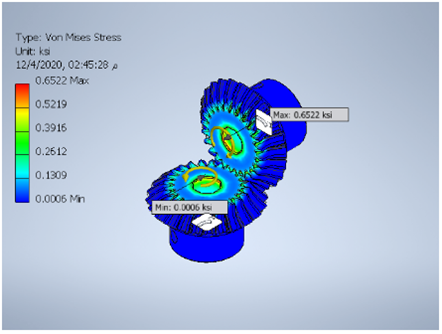
Calculated Stress on Gears designed

Deformation from Calculated Stress
This Project was a great experience from a design concept to a working prototype. The added difficulty of this project was that it was done in the middle of a pandemic, and therefore funding for this project was limited to only $500 dollars since the Washington State Natural Resources budget was low due to cuts, so the team was very limited in what we could do and had to budget well for this project. My team was very successful in coming up with creative solutions to problems. One particularly nasty problem was the challenge of having to drill a square hole! We contemplated casting a part or having a part machined to solve the problem, but both proved to be too expensive so we ended up drilling a 4 mm hole and filed out the corners to make a square hole. By utilizing these solutions the team was able to keep the design under budget and had a surplus of $164.91 after the completion of the project.
This was a team effort, as such, I had various responsibilities and sections that I worked on:
Designed the bevel gears to match a specified set of safety factors
Was one of the designers and modeled the design in AutoDesk Inventor
Gave the original idea for the design as well as designed and 3-D printed out the blade guard
Performed stress and deformation analysis on the prototype
Helped to manufacture and put together a successful working prototype
As the team secretary, I was responsible for scheduling team meetings and directed communication within the team as well as creating a schedule for different phases of the project
We were so successful at our scheduling that we were the first team to complete our prototype in the manufacturing stage whereas other teams had to work up to the last minute to fine-tune their designs and in some cases weren’t able to finish their projects
Personally wrote over 65 pages of the prototype report
AUTOCAD INVENTOR School WORK
This section is a focused look at some work and assignments that I worked on throughout my academic career using Inventor
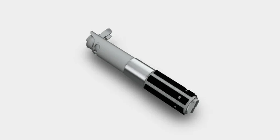
Lightsaber Hilt Assembly
Lightsaber Hilt
This was my final project in my Inventor class. Initially, the requirements were to replicate a wine opener or to take a manufactured product that consisted of three pieces. Being the type of person that looks for a challenge, I decided to do a manufactured product in order to test my skills. I love Star Wars so I decided to measure and model a lightsaber hilt that I have! Criteria for this project included
Parametric Relations
Fully Constrained Sketches
Geometric Constraints
Minimum features of:
Two Revolved Features
Two Circular Pattern Features
One Mirror Feature
One Fillet
One Offset Feature
One Loft Feature
One Spiral Feature
Title Features
Three views per drawing and including one section view and one auxiliary view
If you click the button below, you will be taken to a viewer where you can see and rotate the lightsaber hilt as well as see an exploded view with all of the different parts.
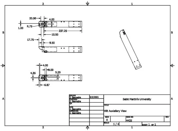
Hilt Auxiliary View
This is a drawing of the hilt showing the measurements used in mm
Assignments
Here is a video showcasing a homework problem utilizing different constraint features in order for the assembly to work together based on the movement of one part. I loved doing this assignment since I love animation, and while it’s very simple and slow, it represents two parts interacting with constraints based on physics.
Tolerances and GD&T
I decided to pick a drawing showing the use of tolerances and for this assignment, GD&T calculations were required when determining the dimensions
Artwork and Photography
Here I wanted to showcase some of my artwork pieces. You might ask yourself why would I include this in my portfolio, however, I wanted to show my creative side that I think highly contributes to any work that I might do.
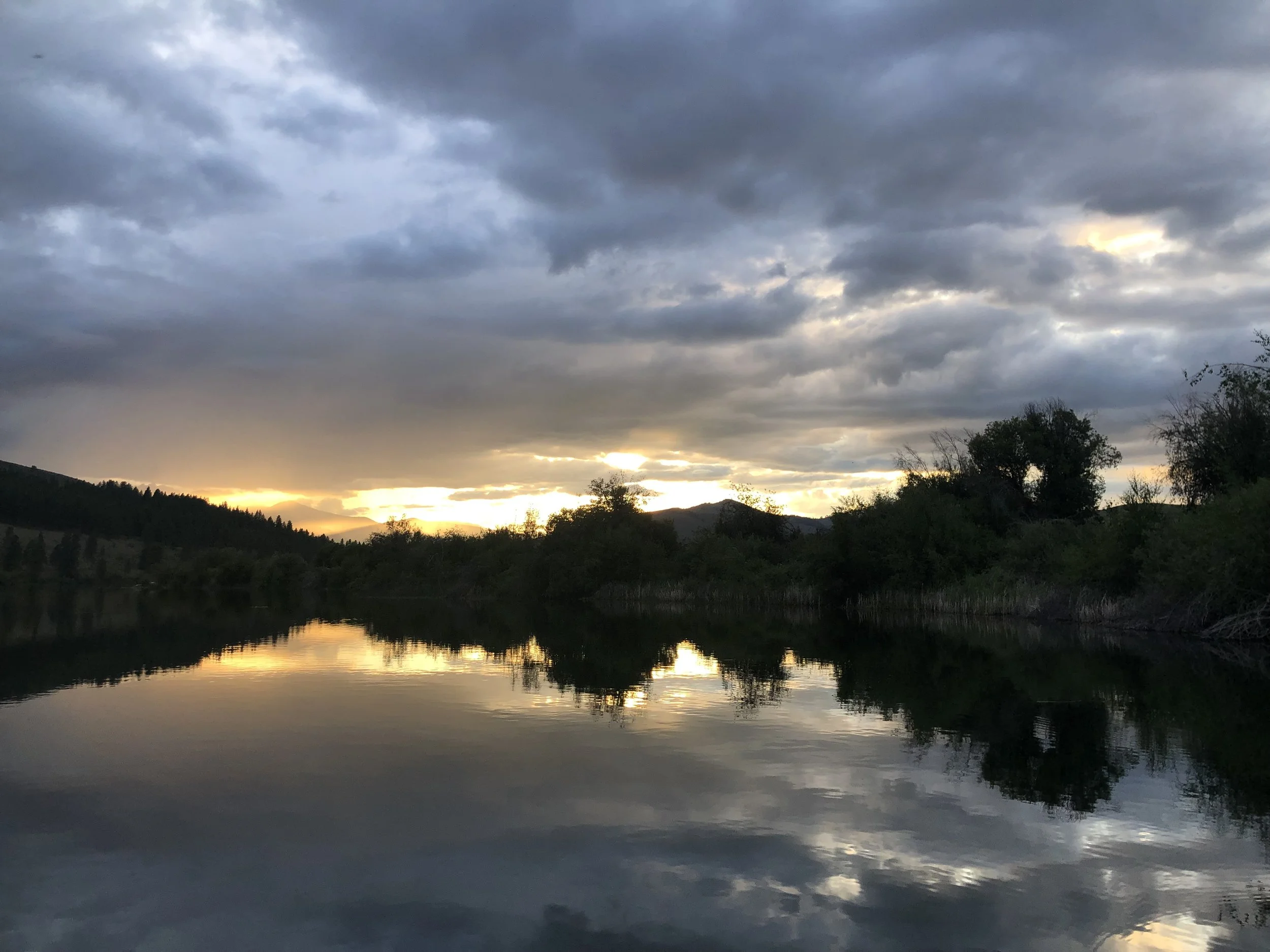
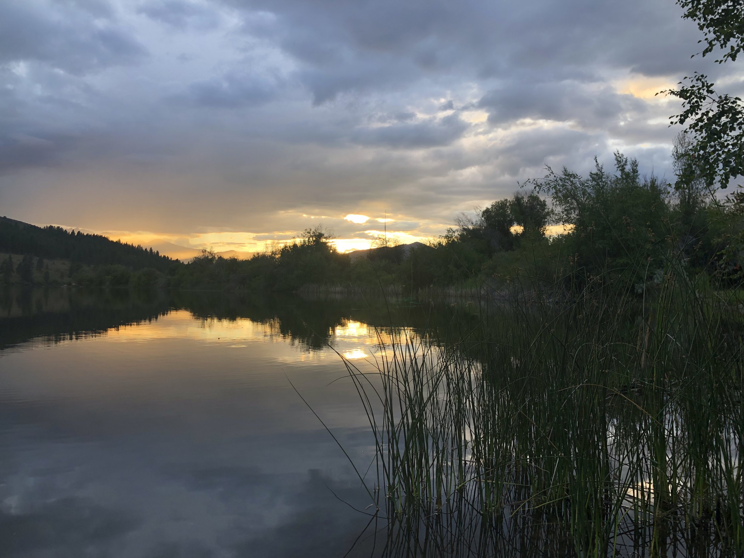
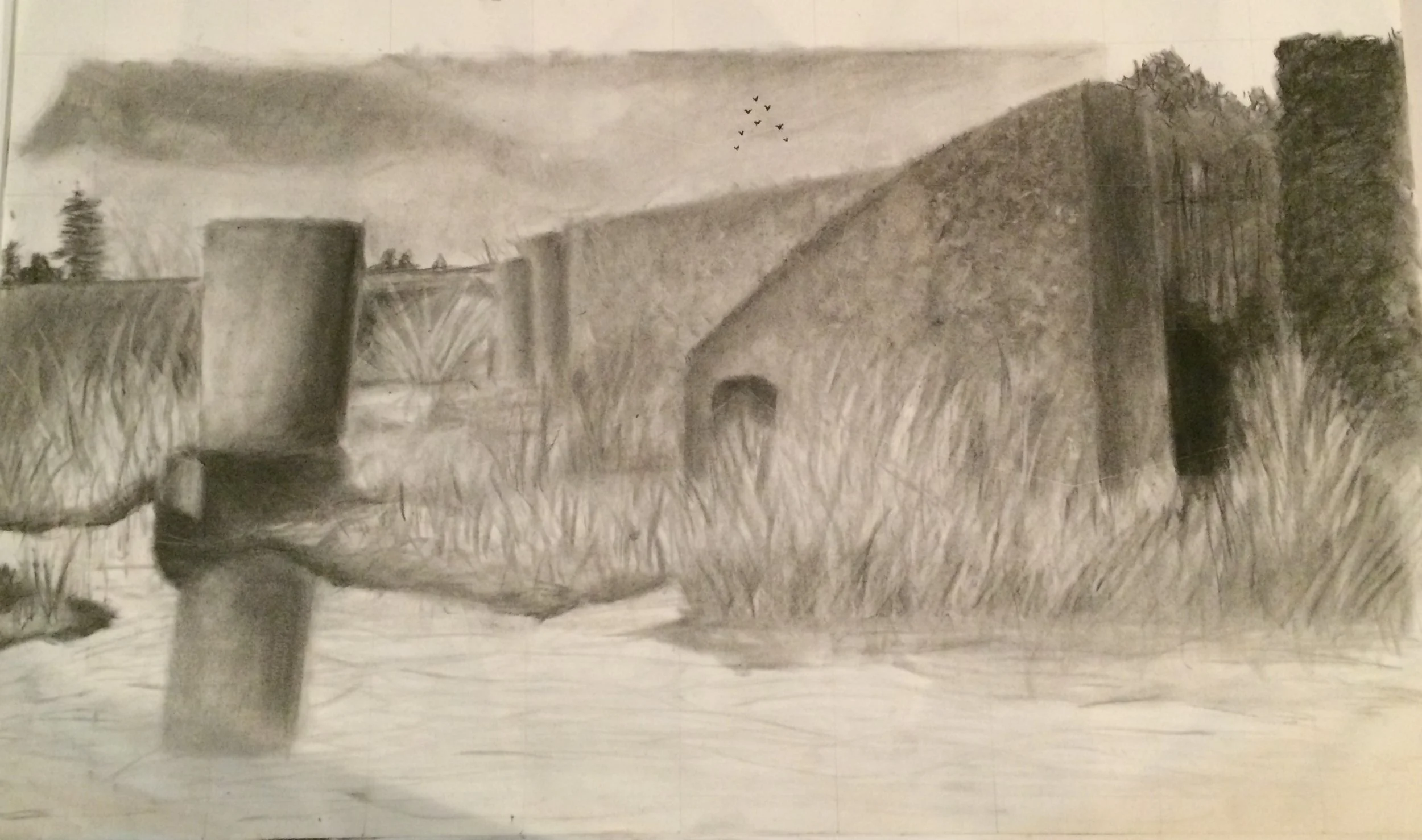
The first picture is an experimentation with the common two-thirds rule, where an object is placed off-center in order to make a piece more interesting. In this case, the outside hedge fulfills this purpose. This piece started with basic shapes, then shading, and finally filling out the details. I also just love the nature aspect of the manmade features of the hedge. Not only that but the simple gray and shading remind me of growing up in Washington where the predominant color 9 months of the year is grey tones or almost in a world slightly asleep.
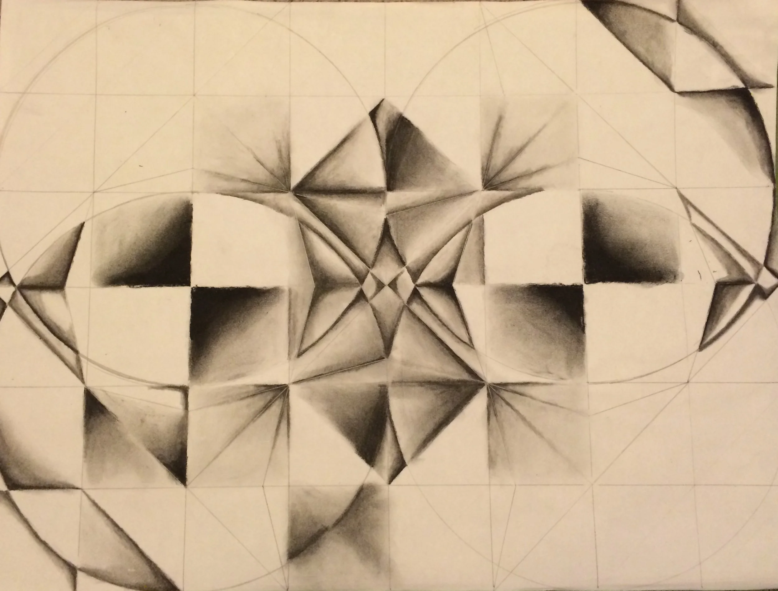
In the second piece I wanted to show some of the processes of making a piece, in this case using geometrical shapes to make something that was pleasing to the eye. I loved working on this piece because it gave me the sense of looking through a kaleidoscope with the ever changing scenes of geometrical shapes.