Project Overview & System Architecture
The Story Behind José | Why This Project Matters | Project at a Glance | System Architecture
THE STORY BEHIND JOSÉ
The Enchanted Tiki Room has always been one of my favorite attractions at Disney. I know it may not be the flashiest attraction in the park, but I have always loved it, and my family has a story about it that has stuck with me since I was a kid.
I remember walking into Adventureland and seeing the Tiki Room for the first time. I had no idea what it was, but between the tikis, the torches, and everything else outside, I really wanted to find out. So naturally, I kept asking my family if we could go inside.
The answer was always, “No.”
Eventually, later in the day, when everyone was hot, tired, and probably just worn down by me asking, they finally gave in.
None of us really knew what to expect.
Then the room came alive.
The birds started singing, the flowers and plants joined in, the tikis started chanting, and even the walls became part of the show. My dad could not stop laughing, and the rest of us were just amazed by everything happening around us.
Ever since then, I have always made time for the Tiki Room when I visit Disney.
As I got older and became an engineer, I started looking at the attraction differently. I still loved the show, but now I was also looking at the mechanisms behind the birds, how everything had to fit inside the figures, how all of those motions had to work together, and how engineering was being used to make something feel alive.
Eventually I had a thought:
What if I tried to build one myself?
That became José.
WHY THIS PROJECT MATTERS
José started because I love the Tiki Room, but I also wanted this project to challenge me as an engineer.
I could have designed a mechanism in CAD, run an analysis, or built a small test fixture and stopped there. Instead, I wanted to build something where all of those pieces had to work together as one real system.
That meant designing compact mechanisms, selecting and sizing actuators, working through loads and motion, using FEA, creating drawings, having parts manufactured, fabricating parts myself, integrating sensors and electronics, designing PCBs, writing motion-control logic, troubleshooting problems, and then actually testing whether everything worked the way I intended.
That is also why this project connects so well with the kind of work I want to do.
Whether it is a spacecraft mechanism, robotic system, automated piece of hardware, or an Audio-Animatronic figure, many of the underlying engineering problems are surprisingly similar. Something has to move. It has to carry load. It has to fit within a limited space. Mechanical, electrical, and control systems have to work together. It has to be built, tested, debugged, and ultimately trusted to work repeatedly.
Those are exactly the kinds of problems I enjoy solving.
José lets me combine two things I care a lot about: the creativity and storytelling that originally made me interested in themed entertainment, and the mechanical design, mechanisms, hardware integration, and testing that draw me toward aerospace, space, robotics, and other complex electromechanical systems.
The goal was never simply to build a Disney bird.
The goal was to see how far I could take an idea from something I loved and turn it into a real engineered system.
PROJECT AT A GLANCE
6 AXES
Five servo-driven figure mechanisms plus an independent worm-geared rotation axis.
90+ PARTS
Parametric Siemens NX mechanical assembly designed around a compact animatronic mechanism and larger installation envelope.
MECHANICAL DESIGN
ASME Y14.5 drawings, GD&T, tolerance planning, mechanism development, actuator sizing, and first-principles load and range-of-motion analysis.
STRUCTURAL ANALYSIS
ANSYS Mechanical static structural analysis including mesh-sensitivity studies, contact modeling, stress-path evaluation, and pretensioned bolted-joint analysis.
FABRICATION & PROTOTYPING
CNC machining, waterjet cutting, tube forming, manual machining, laser-cut fabrication tooling, PETG/nylon additive manufacturing, custom jigs, and mechanical assembly.
ELECTROMECHANICAL INTEGRATION
Raspberry Pi 5, dual Teensy 4.0 controllers, custom KiCad PCBs, servo and DC motor control, quadrature encoder feedback, Hall-effect homing, telemetry, and independently controlled motion-power systems.
CURRENT STATUS
Major mechanical design and fabrication are substantially complete. The independent rotation axis has completed bench commissioning, multiple figure mechanisms have undergone motion testing, and full-system electrical integration, coordinated motion testing, theming, and final verification are still in progress.
SYSTEM ARCHITECTURE
José is a six-axis electromechanical animatronic system made up of five servo-driven mechanisms inside the figure and a separate motorized rotation axis below it.
The five figure mechanisms control body rotation, head tilt, lower-beak motion, body swing, and chest movement. Below the figure, a worm-geared DC motor drives the perch and upper assembly through a belt-driven vertical shaft supported by pillow-block bearings.
Control of the system is divided between a Raspberry Pi 5 and two Teensy 4.0 microcontrollers. The Teensys handle the lower-level motion hardware, while the Pi acts as the higher-level controller for the overall system. Encoder feedback and a Hall-effect sensor support position control and homing of the rotation axis, while custom PCBs handle motion control, power distribution, sensing, telemetry, and system interfaces.
The electrical system uses separate 12 V, 7.4 V, and 5 V power domains, with the motion hardware separated from the always-on logic and supervisory electronics. This allows the system to remove power from the actuators while keeping the controllers, sensing, and monitoring hardware alive.
One of the biggest goals throughout the design has also been serviceability. José was not designed as one giant assembly that has to be completely torn apart every time something needs to change. The mechanisms, electronics, rotation system, and supporting structure were developed as separate subassemblies so they could be built, tested, modified, and debugged individually before everything is brought together into the final system.
MECHANICAL DESIGN, ANALYSIS & FABRICATION
CAD & PACKAGING | GD&T & DRAWINGS | FIRST-PRINCIPLES ANALYSIS | ANSYS MECHANICAL | MANUFACTURING
CAD & PACKAGING
Once I decided I was actually going to build José, one of the first big challenges was figuring out how everything was going to fit.
An animatronic figure gives you a surprisingly small amount of space to work with, especially when several mechanisms all need to move independently without interfering with each other. I had to package five servo-driven mechanisms inside the figure while also leaving room for the structure, bearings, shafts, linkages, wiring, and eventually the exterior shell.
The mechanical system grew into a 90+ part parametric Siemens NX assembly. I used the CAD model not only to design individual parts, but also to work through clearances, mechanism placement, assembly order, service access, and the interfaces between the figure, perch, rotation system, and supporting structure.
One thing I tried to keep in mind throughout the project was that José needed to be something I could actually work on after it was assembled. I did not want to build a mechanism that technically fit together but had to be completely torn apart every time I needed to make an adjustment. That led me toward smaller, serviceable subassemblies that could be removed, tested, and modified independently.
A lot of the design changed as the physical hardware came together, but having the full system modeled in NX gave me a place to work through those changes before cutting or remaking parts.
GD&T, DRAWINGS & TOLERANCE PLANNING
Getting something to fit together in CAD is one thing. Getting real manufactured parts to fit together the same way is another.
For the parts that needed outside manufacturing, I created ASME Y14.5 engineering drawings with GD&T and tolerance planning so that the design intent was not dependent on someone looking at the CAD model and guessing what mattered.
That became especially important around shafts, bearings, mounting holes, mating components, and other areas where small dimensional changes could affect alignment or motion.
The drawings also forced me to think more carefully about how each part would actually be manufactured and inspected. Instead of simply asking, “Does this dimension look right in CAD?” I had to think about which surfaces and features actually controlled the function of the part and how much variation the mechanism could realistically tolerate.
That process helped bridge the gap between designing a mechanism and designing hardware that someone else could manufacture and I could reliably assemble.
FIRST-PRINCIPLES ENGINEERING
I did not want actuator selection or structural decisions to come down to simply choosing something that looked large enough and hoping it worked.
Before fabrication, I used first-principles torque sizing, load calculations, and range-of-motion studies to help size the mechanisms and select the servos. The five digital servos were evaluated around things like torque, speed, packaging, acoustic performance, and how they would actually be used in the figure.
The same thinking carried into the rest of the mechanical system. I worked through forces, moments, geometry, available motion, and the load paths through the mechanisms before relying on simulation.
For me, the calculations and the CAD serve different purposes. The math helps tell me whether the basic engineering makes sense. The CAD tells me whether I can actually package it. FEA then gives me another tool for looking more closely at the structural behavior of specific parts and assemblies.
Using all three together has been much more useful than treating any one of them as the answer by itself.
ANSYS MECHANICAL
One of the areas I wanted to develop further with José was structural analysis in ANSYS Mechanical, so I used the head-tilt servo support assembly as a case study.
The analysis started as a relatively simple linear static model, but it became much more interesting once I started checking whether the model itself was actually behaving the way I expected.
During model verification, I discovered that ANSYS mesh defeaturing had removed the servo body from the finite-element load path. That meant some of the earlier results were not representing the physical assembly correctly. I corrected the model, reran the baseline cases, verified reaction-force equilibrium, and then continued the analysis using the corrected load path.
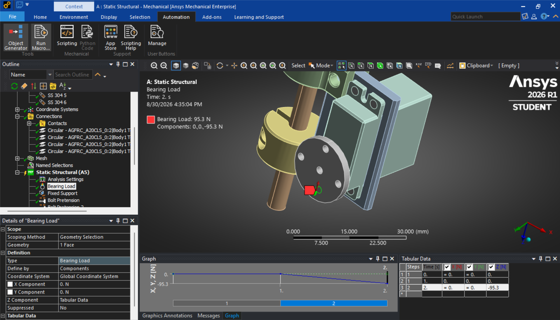
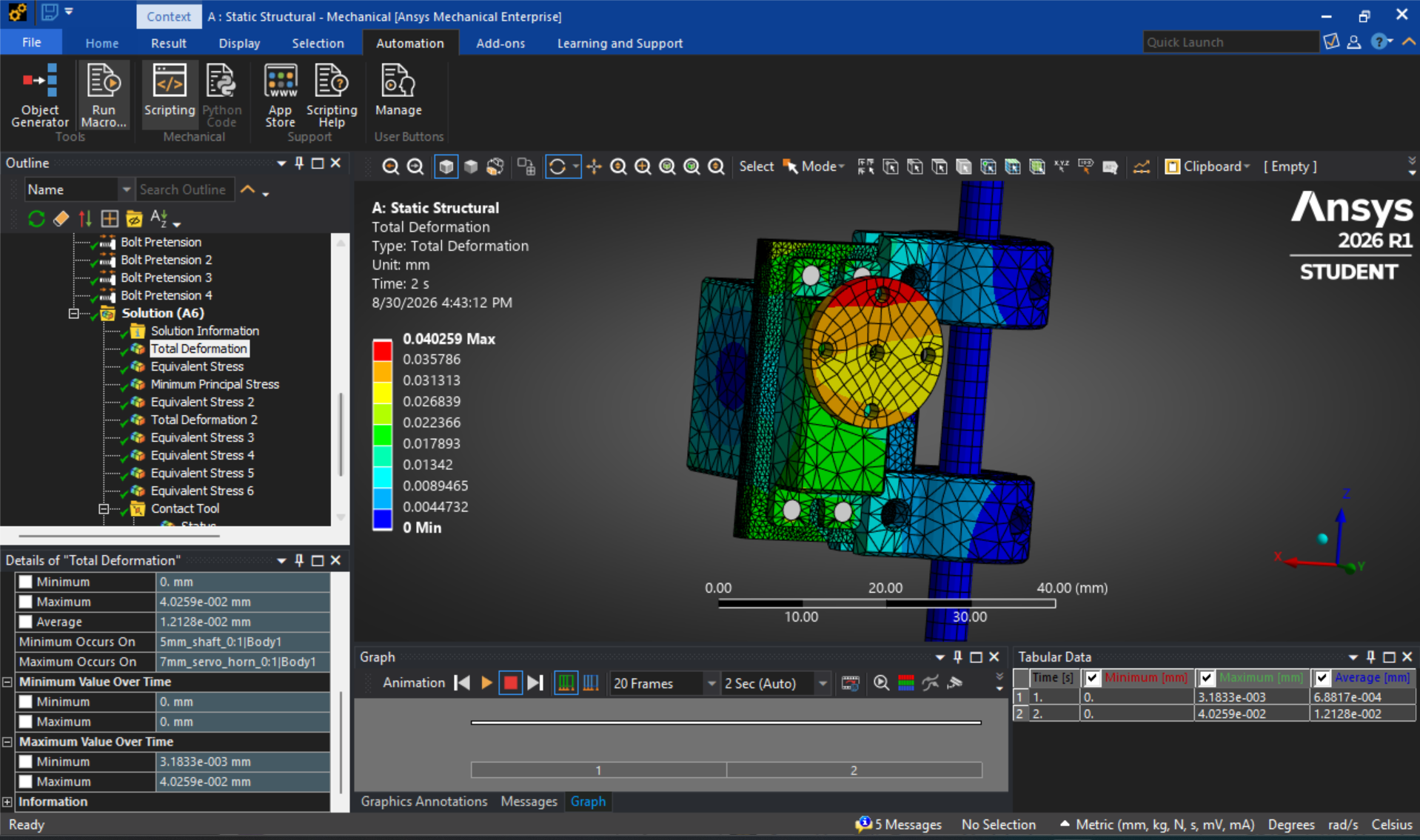
From there, I used the servo stall torque and verified horn radius to develop a 95.3 N theoretical stall-equivalent load case. I evaluated stress, deformation, mesh sensitivity, and stress paths to understand whether the highest reported stresses represented broader structural loading or very localized interface effects.
The study eventually progressed from simplified bonded interfaces into a higher-fidelity joint model using frictional contact, four M2.5 fastener representations, bolt pretension, and multi-step loading. I then evaluated von Mises stress, deformation, contact pressure, sliding, and penetration around the joint.
One of the more useful lessons from the analysis was learning not to simply accept the highest stress value ANSYS gave me. Refinement showed that some of the largest local peaks were highly sensitive to the contact and interface assumptions, while the broader structural response was much more stable.
That changed how I interpreted the model.
Instead of using a colorful stress plot as proof that the design was “good,” I used the analysis to understand the load path, identify where the model was sensitive, improve the joint representation, and separate meaningful structural behavior from local modeling effects.
The current analysis is useful for understanding stiffness, load transfer, and joint behavior, but I do not treat it as final physical validation of the hardware.
MANUFACTURING & FABRICATION
José was never meant to stay inside the computer.
A large part of this project has been taking the CAD models and drawings and figuring out how to turn them into real hardware using a mixture of outside manufacturing and fabrication I could do myself.
For precision aluminum components, I sourced CNC-machined and waterjet-cut 6061-T6 parts, including sending RFQs to multiple vendors and receiving successful first-article CNC hardware.
For the parts I fabricated myself, the project has involved drilling, tapping, reaming, tube forming, manual machining, soldering and brazing, laser-cut fabrication tooling, and additive manufacturing.
I also designed eight custom 3D-printed drill jigs to help keep M2 through M4 fastener patterns aligned and repeatable during fabrication. PETG and nylon printed parts were incorporated throughout the mechanism, along with heat-set inserts where I wanted stronger or more serviceable threaded connections.
The perch and support structure created another type of fabrication problem. I used CAD-derived bend profiles and laser-cut plywood templates to help form the tubing, then added the required joints, mounting features, and wire-routing holes so the finished structure could support both the mechanism and the concealed electrical routing.
That combination of CAD, drawings, vendor manufacturing, fixtures, and hands-on fabrication has probably been one of the most valuable parts of José for me.
Every step exposes something different.
CAD might show that two components fit. Manufacturing tells you whether the geometry is practical. Assembly tells you whether you can actually reach the fasteners. Motion testing tells you whether the clearances you thought you had are really enough.
The design has continued to change because of what I learned once the parts became real, and that has been exactly the point of the project.
MECHANISMS & MOTION SYSTEMS
SERVO MECHANISMS | LINKAGE DEVELOPMENT | HINGE REDESIGN | WORM-DRIVE ROTATION | encoding & homing | COMMISSIONING
SERVO-DRIVEN MECHANISMS
One of the main reasons I chose José as a project was that I wanted to work on mechanisms that actually had to move together inside a very limited space.
The figure uses five servo-driven axes for body rotation, head tilt, lower-beak movement, body swing, and chest movement. Each one presented a slightly different problem. Some needed compact linkages, some needed more torque, some were limited by the available space inside the figure, and some had to be designed around the movement of another axis.
That made servo selection more involved than simply choosing one based on torque alone. I also had to consider speed, size, mounting geometry, available range of motion, duty cycle, noise, and how the actuator would actually fit into the mechanism.
The internal structure eventually became a combination of aluminum plates, shafts, bearings, brackets, linkages, printed components, and custom mounting hardware. A lot of the challenge came from getting all of those mechanisms to occupy the same small space without interfering with one another.
This was also one of the areas where CAD could only take me so far. Once the mechanisms were assembled and actually moving, I started finding things that were not obvious when everything was still on the screen.
Hinge redesign
The head-tilt mechanism went through a similar process.
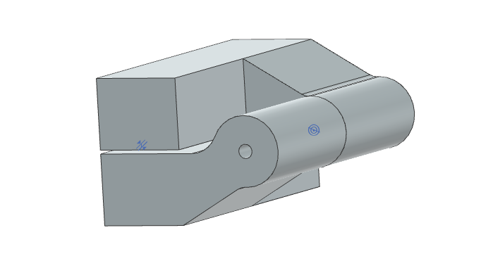
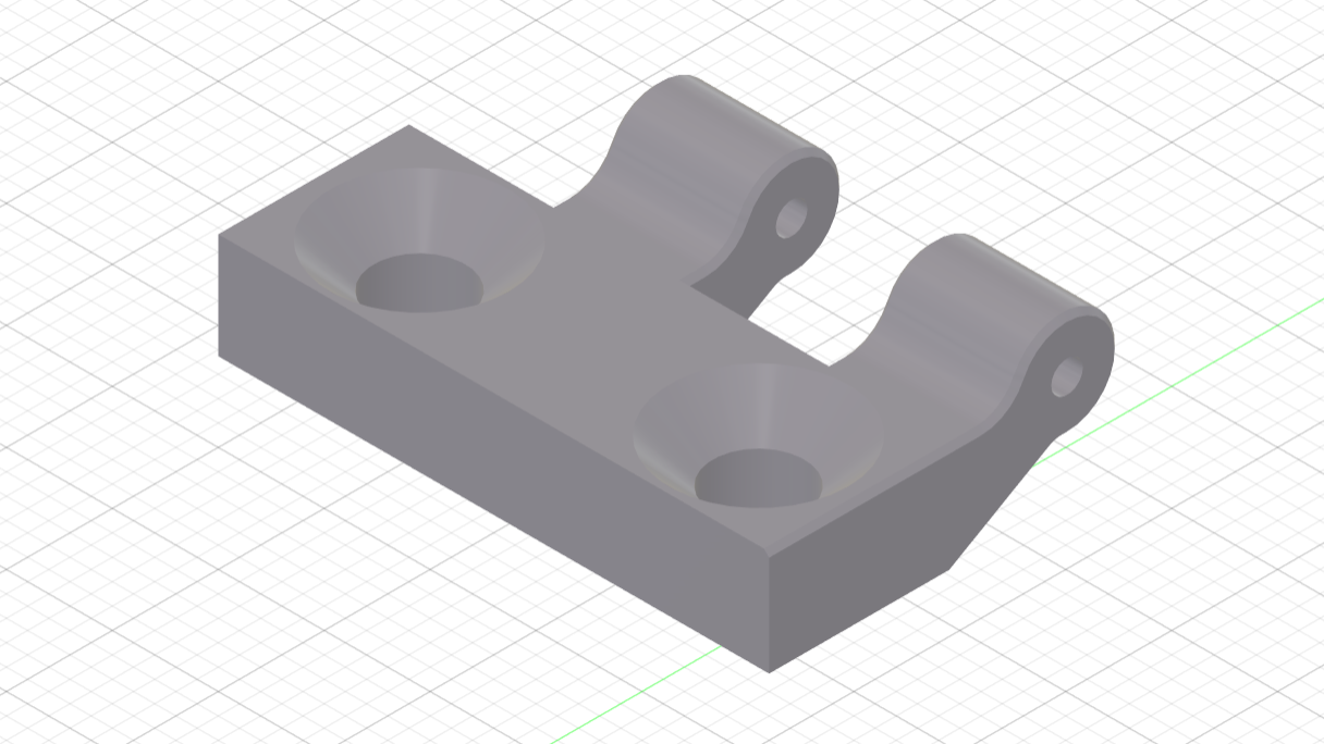
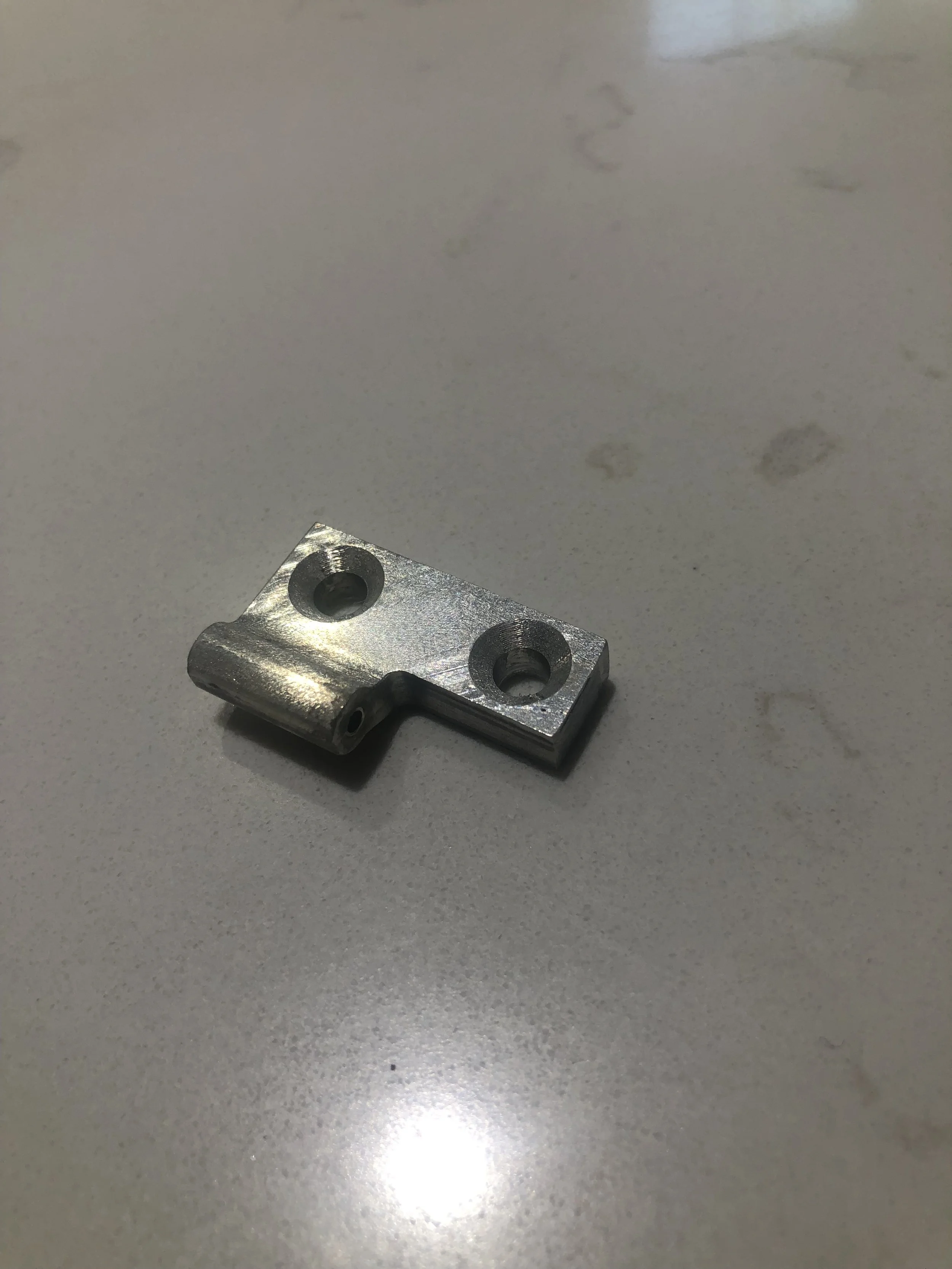
The original hinge used a two-ear arrangement with an E-clip retained pivot. It worked, but once the assembly was built I was not happy with the amount of axial play in the joint or with how the loads were being carried through the hinge.
I redesigned it into a four-ear captured-pin configuration.
The new arrangement distributed the load through more of the hinge structure, reduced the axial play I was seeing, and removed the external retaining hardware from the joint.
The head-tilt system also had another challenge: balance.
Once more of the real head assembly was installed, the mechanism became increasingly front-heavy. That changed the loads the servo was seeing and made it obvious that the final mechanism could not be evaluated using only the lightweight development geometry.
I worked through the balance using counterweight and spring assistance while continuing to test the mechanism with progressively more representative hardware installed.
That is also why I used the head-tilt support assembly for the ANSYS work in the previous section. It is a relatively small mechanism, but it combines actuator load, linkage geometry, bearings, brackets, fasteners, balance, and structural stiffness in one place.
LINKAGE DEVELOPMENT
One of the best examples of that was the linkage system.
The original linkage geometry worked in CAD, but during incremental motion testing I started seeing binding as the mechanism moved through different angles. The connection was too constrained and could not accommodate the angular changes happening between the servo arm and the driven mechanism.
That led me to redesign the connection around an M2.5 ball-end joint.
It was a relatively small change, but it made a big difference in how the mechanism behaved because the joint could now tolerate angular misalignment instead of forcing the rest of the linkage to absorb it.
That experience became a good reminder that a mechanism can look completely reasonable when viewed at one position in CAD and still behave very differently once it starts moving through its full range.
A lot of José has developed that way.
Build something. Move it. Find the part that does not behave the way I expected. Figure out why. Change it. Test it again.
COMMISSIONING
This was the first part of José that I treated as a complete motion subsystem rather than just asking, “Does the motor turn?”
I wanted to know:
Where does the mechanism think it is?
How repeatable is that position?
What happens when it approaches the same location from opposite directions?
Where is physical home?
How does the Hall sensor behave at different motor speeds?
How much of the measured positioning is encoder accuracy, and how much is actual mechanical repeatability?
That commissioning process changed the way I thought about the project.
Getting a mechanism to move is only the beginning. Getting it to move to a known position, return to a reference, stop where expected, and behave the same way repeatedly is a completely different engineering problem.
And that is really what I wanted José to become: not a collection of moving parts, but a system where the mechanics, sensors, controls, and testing all support one another.
WORM-DRIVE ROTATION SYSTEM
The sixth axis is separate from the five mechanisms inside José.
Instead of rotating only the figure, I wanted the entire upper perch assembly to rotate. That meant building a much larger motion system capable of supporting the figure and structure while still giving me controlled movement and a repeatable home position.
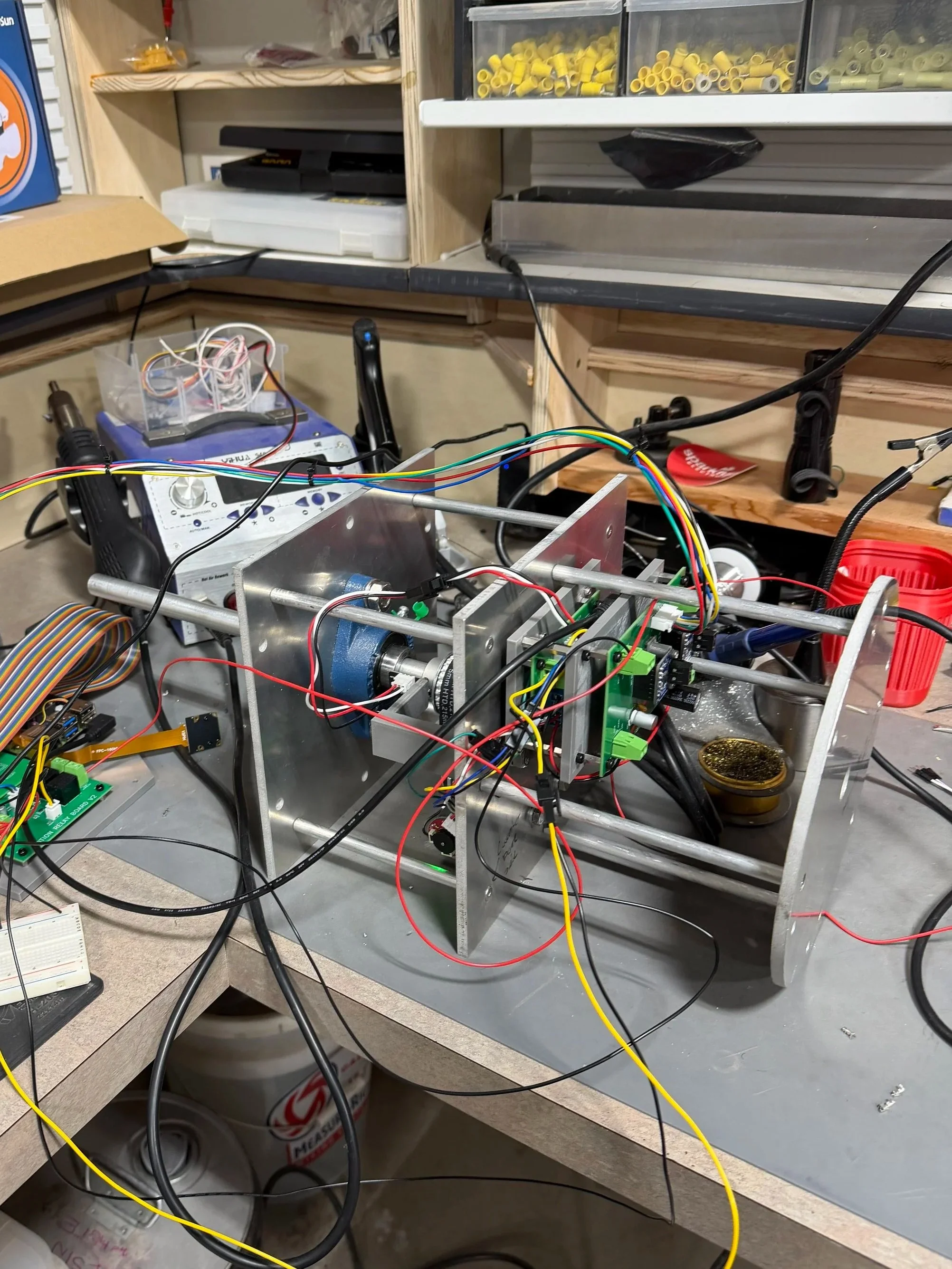
The rotation system uses a 12 V worm-geared DC motor driving a belt transmission connected to a 5/8-inch aluminum vertical shaft. The shaft is supported by pillow-block bearings mounted into a structural frame made from waterjet-cut plates and aluminum standoffs.
I added machined shaft flats, pulley retention, belt tensioning, and mounting features so the system could be adjusted and serviced rather than permanently fixed into one configuration.
The worm gear was useful for another reason as well: it gave the axis a large reduction while helping the system resist back-driving when it was not moving.
Unlike the figure servos, though, the DC motor did not give me position information by itself.
That meant I needed to turn it into a controlled axis.
ENCODER FEEDBACK & HOMING
For position feedback, I integrated the motor's quadrature encoder and used repeated full-revolution testing to determine the actual encoder count for the mechanism.
The measured value settled at 58,900 counts per revolution, or approximately 163.61 counts per degree.
From there, I tested commanded positions at -60°, 0°, and +60° across repeated unloaded bench runs. Encoder-reported position error remained below 0.1° across the eight tested positions, while physical observation showed approximately 1° of direction-dependent repeatability.
The difference between those two numbers was important.
The encoder could tell me very accurately what the motor and drivetrain believed the position to be, but the physical system still contained belt compliance, backlash, structural movement, and other real-world effects that do not appear in the encoder count alone.
For the home reference, I added a Hall-effect sensor and magnet to the rotation system.
Rather than simply stopping the first time the sensor changed state, I characterized the magnetic field edges from both directions and at several motor-output levels. That let me identify the center of the sensed field and use that midpoint as the physical home reference.
I am still refining the complete automatic homing sequence, but the sensor characterization and encoder calibration established the basis for a repeatable startup reference.